Description
The VKL 10 series of dilution systems can reduce the concentration of aerosols by the dilution factor 01:10, also of very highly concentrated aerosols, in a defined and reliable way.
The Palas® VKL 10 dilution systems are used in vertical operation for the particle size range up to 20 µm for powders and dusts. Dilution factors of up to 1:100,000 are achieved by cascading several VKL systems.
Functional principle
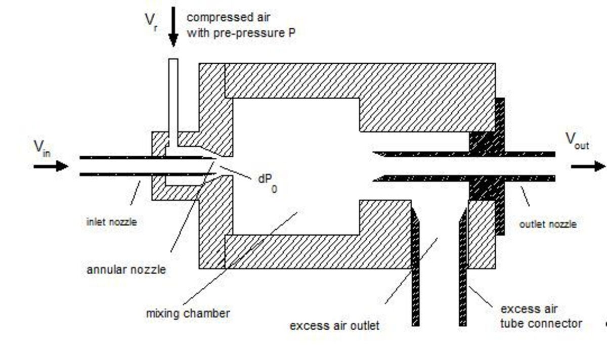
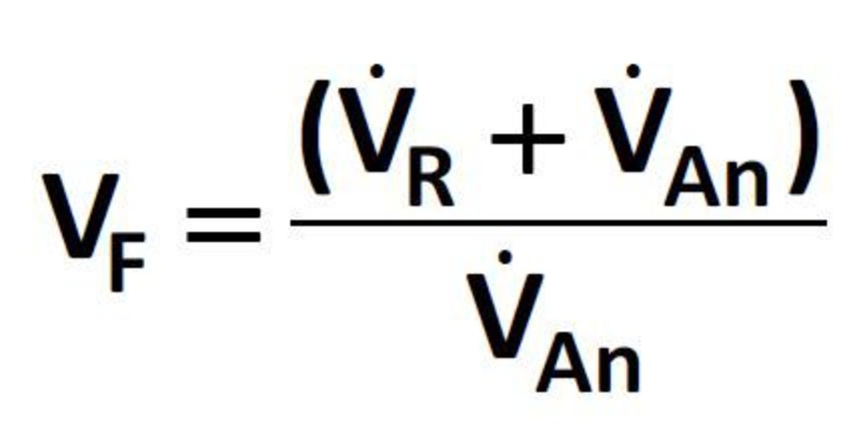
Particle-free air with the volume flow VR circulates through an annular passage around the suction nozzle. Thus, according to Bernoulli, a volume flow VAn is generated at the suction nozzle.
The dilution factor VF is calculated according to the following formula
Representative dilution of particle size distribution of the Palas® dilution systems by cascading
VDI report no. 1973 from 2007 proved metrologically that a reproducible aerosol dilution is possible with the Palas® dilution systems down to VF 100,000.
Simple functional test on-site
With this simple test set-up, the Palas® cascaded dilution systems can be checked by anyone themselves:
Firstly a particle measurement is performed with one dilution step. Here it is important that the aerosol concentration, e.g. lab air, to be measured does not exceed the coincidence limit (maximum detectable aerosol concentration). In the second step, the dilution step to be tested is connected in series (cascaded). To check the dilution factor of the test step (pos. 2), the total particle count form the measurement in pos. 1 is divided by the total particle count from pos. 2.
Experimental setup
![]()
Position 1: Lab air
![]()
Position 2: Lab air
The VKL 100 serves to measure coincidence-free with the OPC; the VKL 10 is tested.
Measurement example
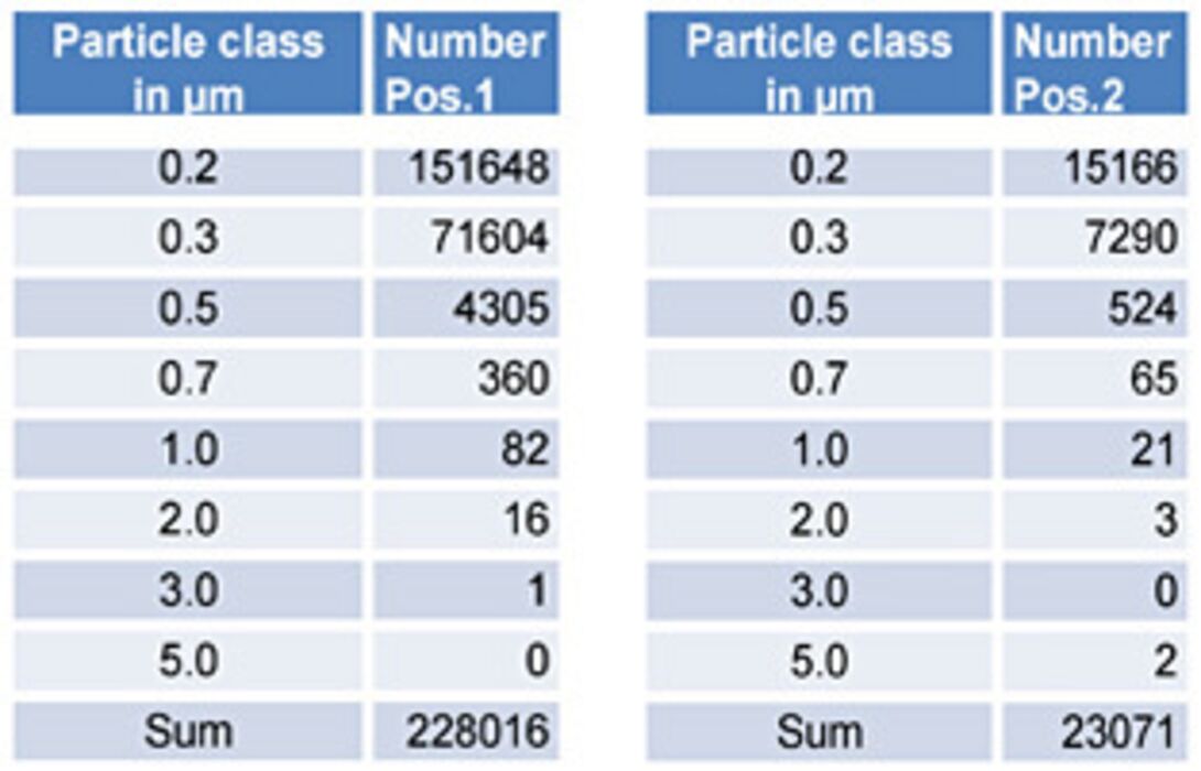
Calculation of the dilution factor
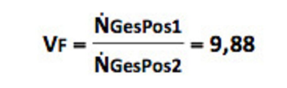
Provided the first measurement is not affected by a coincidence error and the dilution system under test is working (not soiled), a dilution factor of almost 10 is determined. If this should not be the case, there was possibly coincidence in measurement 1. In this case the aerosol concentration has to be decreased or a further dilution step used. Another possibility would be that the dilution step to be tested is soiled. In this case the device has to be cleaned and the test repeated.
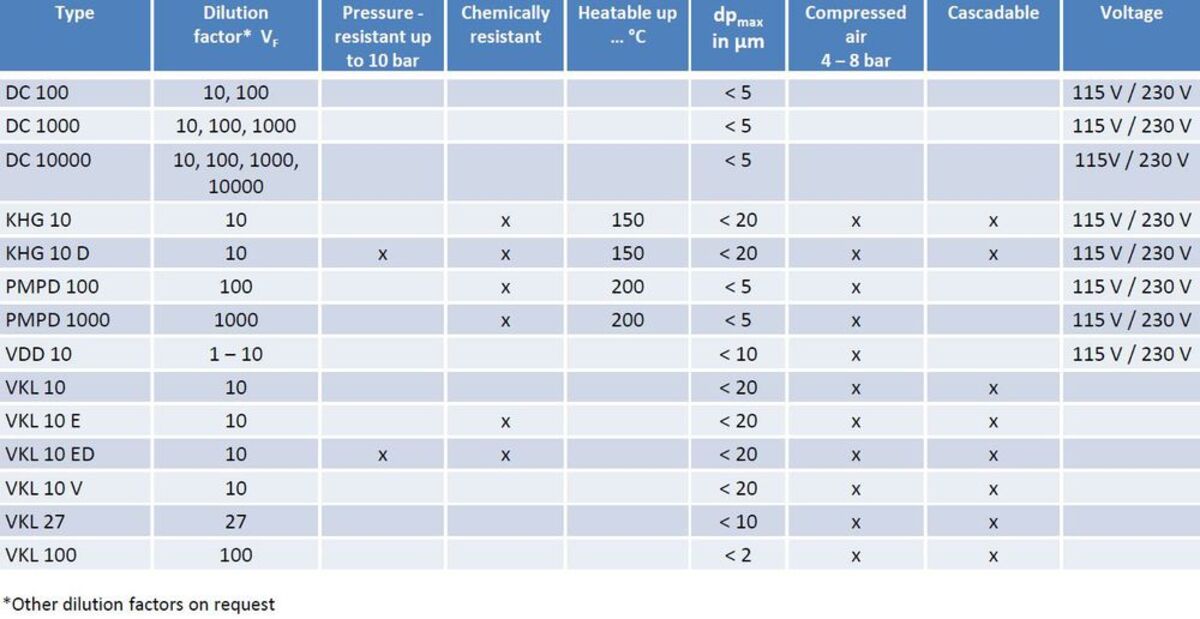
Table 1: Technical characteristics of Palas® dilution systems